The photo above is a Twiggy Mk1 from France

This presentation documents the construction of a modified version of Lock Crowther's famous Twiggy Mk 2 trimaran

Monday, December 8, 2014

Mainhull stringers, gunnels, keel

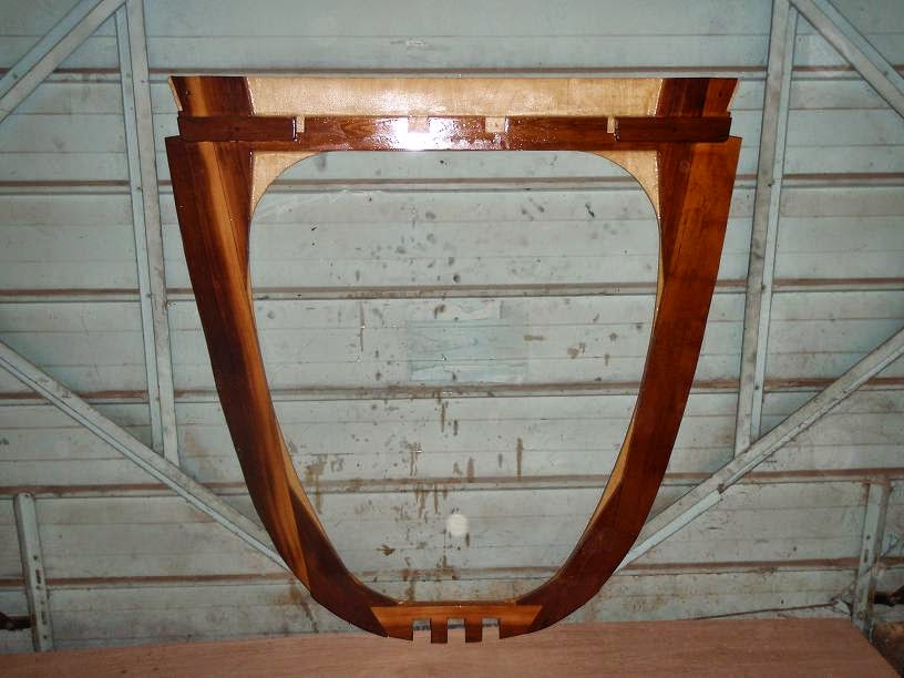
10 stringer scarfs clamped at once

epoxy has cured, clamps removed,
strips of wax paper separate the stringers


finished scarfs have been belt sanded 

stringers scarfed to full length are fed through the router with a round-over bit

rounded side will face inboard


two coats of epoxy on each stringer, gunnel, keel piece

Friday, August 15, 2014

Mainhull frame 6 to transom - upper portions

frame 6 - forward side (head / shower)
you can see where the lower portion will scarf on

frame 6 - aft side
the timber reinforcing compensates for weakening caused by the cutouts
and also provides framing for dividers and ceiling under the forward crossbeam

frame 7 - forward side

frame 7 - aft side (galley)
you can see where the lower portion will scarf on

frame 8 - forward side (galley)
the lower portion will scarf onto the vertical timbers at each side of the hull

frame 8 - aft side

frame 9 - forward side (companionway)
extra timber reinforcing at the mast step / central deck stringer

frame 9 - aft side (cockpit)
the timber pieces for the cockpit seats are not glued yet
they will be removed to ease the scarfing operation
once the top and bottom portions of frame 9 are scarf glued together, 
then the timber pieces can be glued on 

frame 10 - forward side (cockpit)
hub for steering is ready
timber pieces not glued yet since they overlap the scarf

frame 10 - aft side
the timber pieces supply framing for a ceiling, 
and dividers under the rear crossbeam
the diagonal channels protect the steering chain / cables

frame 10 - steering installation
the fiberglass shield will cover and seal in a large stainless washer used
to attach the bulkhead steerer

frame 10 - steering channel
you can see the hole drilled in line with the steering channel
where the cable will pass thru the frame timber 
into the gunnel area and then over a pulley to the rudder area

frame 11 - forward side
you can see where the dividers will be glued in,
 creating 4 storage compartments under the rear crossbeam

frame 11 - aft side
you can see where the lower portion will scarf on

  • Note: there is no upper portion at frame 12
  • a large pop top hatch will span across the deck here
  • the hatch will incorporate a beam to support the deck / roof over the frame 12 area
  • the pop top hatch will extend from frame 11 to frame 13
  • making it about 5' x 7' and giving standing headroom in the aft cabin when popped up


h 
frame 13 - forward side

frame 13 - aft side


Friday, August 1, 2014

Mainhull frames 1 to 5 - upper portions

frame 4 - forward side
you can see where the lower portion of the frame will overlap and glue on 
the center of the frame is open for a 24" deck hatch
(these halves will be farther apart in the setup)

frame 4 - upper portion - aft side

frame 5 - upper portion - forward side
you can see where the lower portion will scarf on

frame 5 - upper portion - aft side


Wednesday, July 30, 2014

Mainhull frames 12 to transom

frame 12 - forward side
there is no cross piece here since this frame is in the middle of the aft cabin

frame 12 - aft side

frame 13 - forward side

frame 13 - aft side

transom - forward side
the 2nd row of notches is for aft cabin berth 

transom - aft side

Sunday, July 20, 2014

Mainhull frames 5 to 11

frame 5 - forward side
frame 5 - aft side
the top 8" of each side will scarf onto the upper portion of frame 5

frame 6 - forward side
frame 6 - aft side
includes framing for galley cabinet
note pilot holes in top corners for quick alignment of scarf to upper section

frame 7 - forward side

frame 7 -aft side
includes framing for galley on port side
and bench seat on starboard side

frame 8 - forward side

frame 8 - aft side
the top 8" of each side will scarf onto the upper portion of frame 8

frame 9 - forward side

frame 9 - aft side
the dagger case glues down the middle between the timber pieces 

frame 10 - forward side
the outer keel notches receive 2 keel timbers on the forward side of frame 10
these straddle the dagger case
the middle notch is for a single keel aft of frame 10 
packing pieces will be glued between them where they overlap

frame 10 - aft side
note pilot holes in top corners for quick alignment of scarf to upper section


Tuesday, July 15, 2014

Mainhull frames 1 to 4


frame 1 - forward side

frame 1 - aft side
nice topside flare

frame 2 - forward side
note bevel along bottom edge
this frame installs 25 deg from vertical, in line with the forestay
the bevel makes a flush joint where it joins frame 1 
frame 2 - aft side

frame 3 - forward side

frame 3 - aft side

frame 4 - forward side

frame 4 - aft side
the top 8" of each side will overlap and glue onto the top section of frame 4
the top section will be attached after the hull is built, 
rolled right side up, and carried out of the shop
headroom in the shop is too low for the hull with cabin.......


Tuesday, July 1, 2014

Mainhull frame 10 steering hub


 steering wheel temporarily fitted and bolt holes drilled


  • the frame is built up with a fiberglassed plywood hub to add strength 
  • and to provide clearance for fingers between the steering wheel rim and the top of frame 10

  • temporary fastener holes filled with epoxy filler and capped with wax paper ensure a flush result
  • note the fancy recesses to accommodate the hub shape